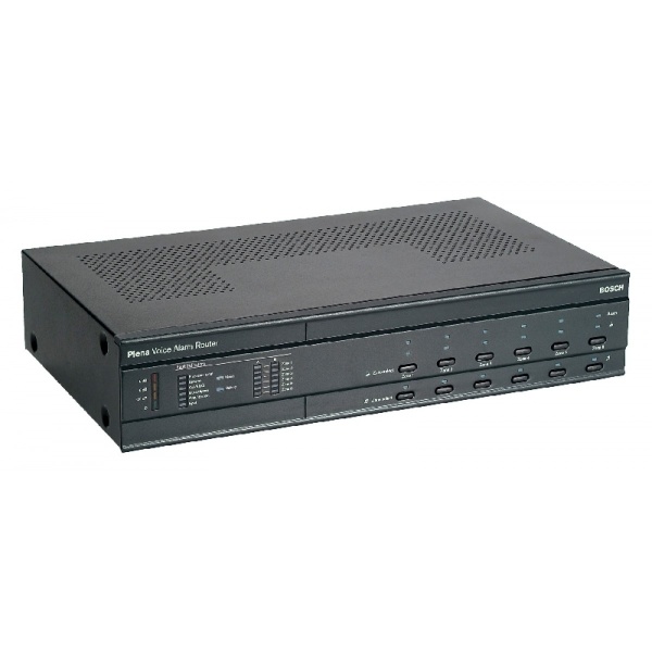
BOSCH LBB 1992/00 Plena Voice Alarm Router
৳ 140,000
-
Model: LBB 1992/00
- Expand the voice alarm system with six zones
- EN 54‑16 certified and EN 60849 compliant
- 12 additional input contacts
- Six volume override output contacts
- Supervision within the Plena Voice Alarm System
- Description
- Reviews (0)
Description
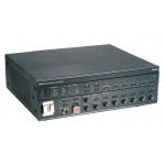
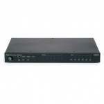
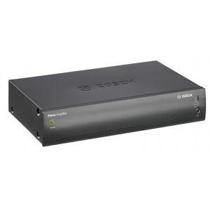
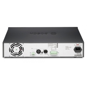
The Plena Voice Alarm Router is an expansion unit that can add six zones and 12 input contacts to the Voice Alarm System. It can use the built-in amplifier on the LBB 1990/00 Voice Alarm Controller, and provides inputs and outputs for one or two amplifiers in a multiamplifier one or two-channel system.
It provides dual channel operation for calls and BGM simultaneously to a maximum of six different zones, using two Plena amplifiers. Additionally, single channel operation is possible with only one Plena amplifier.
Multiple routers can also share one amplifier, including the internal amplifier on the controller unit. It is possible to use any number of amplifiers from one up to the number of routers used. The controller supports A/B wiring.
Functions
The LBB 1992/00 has a set of relays for zone-switching the power amplifier output(s) to different loudspeaker groups. Each zone can be switched between:
• The call channel (call-station selection, all-call microphone, or emergency activation)
• The BGM channel (front panel selection)
• Off
Volume override relay contacts are provided for each zone separately for overriding local loudspeaker volume controls. This ensures that priority messages go through with a given volume, even though the local volume controls may be set to a low volume level for background music, for example. Both three-wire and four-wire override schemes are supported. A call or a triggered input will activate these contacts for the appropriate zones, together with an additional voltagefree contact (call-active) for control purposes.
An overload protected 24 VDC output provides power for driving external relays, making an external power supply unnecessary. The master output channel, or one of the input channels, can be selected to be monitored with headphone connector and LED meter.
Controls and indicators
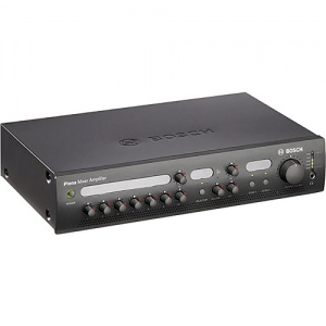
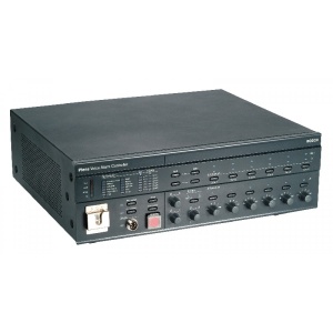
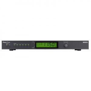
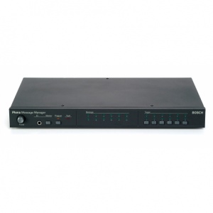
Front
• Meter (LED’s for -20, -6, 0 dB and Power ON)
• Eight system fault LEDs
• 12 loudspeaker line fault LEDs
• Six EMG call-zone selection buttons
• 12 EMG call-zone status LEDs
• Six BMG zone selector buttons
• Six BMG zone status LEDs
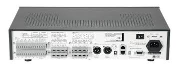
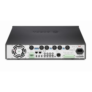
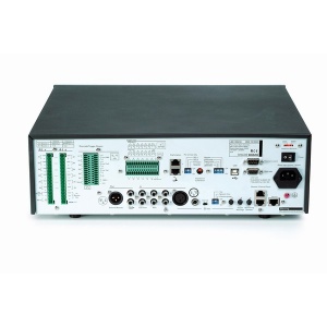
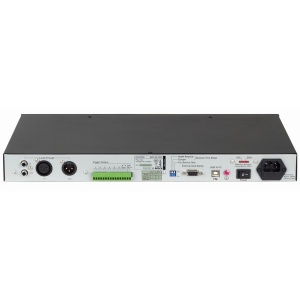
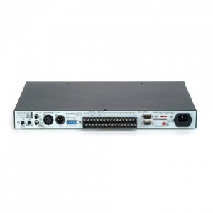
Back
• 2 x DIP switch
• Unit ID rotary control
• Mains voltage selector
• Power switch
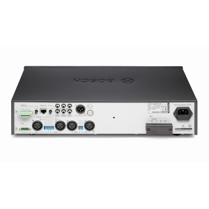
• Mains socket Interconnections Back
• 12 loudspeaker outputs
• Two external amp inputs
• Call output
• Six volume override outputs
• 12 trigger inputs
•RS-232 connector
• Two system interlinks
• Two external amp outputs (XLR/balanced)
• Power amp fault output
• 24 VDC power output
• 24 VDC power input
• Two extra trigger outputs
• Earth connection screw




Reviews
There are no reviews yet.